
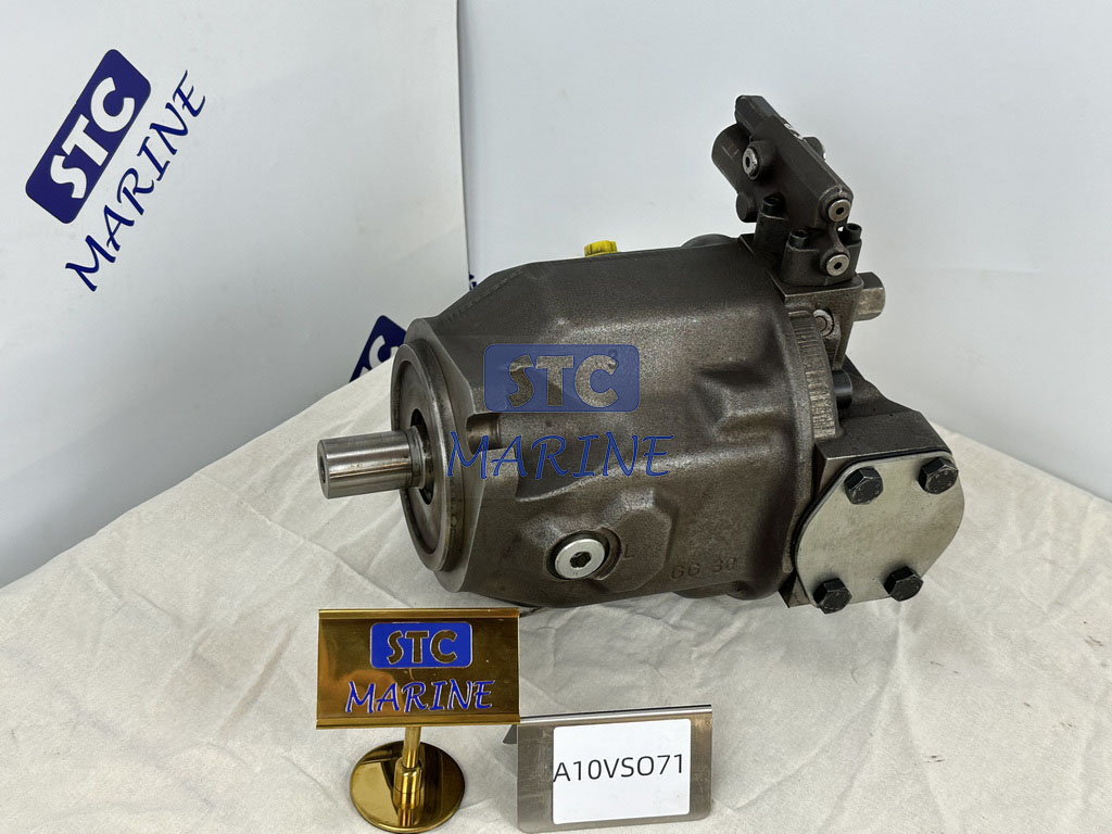
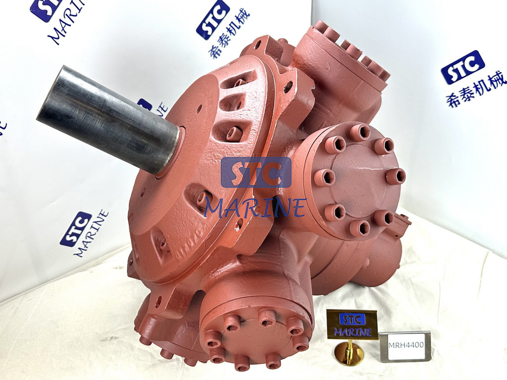

Hydraulic pumps convert mechanical energy from an engine or electric motor into hydraulic energy in the form of fluid flow. The pump creates a low-pressure zone at the inlet, drawing hydraulic fluid from the reservoir and trapping a defined volume of oil. This oil is then forced into the hydraulic circuit, where pressure is created when it meets resistance from a load, valve, or actuator. This explanation is consistent with that given in several established references on hydraulics, including Anthony Esposito’s Fluid Power with Applications, the Bosch Rexroth Industrial Hydraulics Manual, and Herbert E. Merritt’s Hydraulic Control Systems. All of these sources emphasise that a hydraulic pump primarily generates flow, while system pressure is a result of downstream resistance.
Hydraulic pump introduction
Hydraulic pumps are one of the most important components in modern fluid power systems. They are used in excavators, agricultural tractors, construction machinery, hydraulic presses, marine equipment, material handling systems, machine tools, and countless other industrial power units. Despite the widespread use of hydraulic technology, many explanations of hydraulic pumps are overly simplified. For example, they often say that a pump ‘moves hydraulic oil through the system’, which is true, but this description is not detailed enough for engineers, procurement teams, equipment manufacturers, or industrial buyers, who need to understand performance, pump selection, efficiency, and failure risks. To understand how hydraulic pumps work, it is necessary to examine the hydraulic cycle itself and follow the process from the moment the shaft begins to rotate until pressurised oil reaches a cylinder or hydraulic motor.
At the most basic level, hydraulic pumps convert mechanical power into hydraulic energy. They do this by repeatedly creating, expanding, and contracting internal volumes that draw in and then displace hydraulic fluid. Since hydraulic oil is effectively incompressible under normal operating conditions, this moving fluid reliably transmits force. However, it is important to clarify one point at the outset because it affects every subsequent design decision: hydraulic pumps do not create pressure by themselves. A pump creates flow. Pressure only appears when this flow encounters resistance, such as a loaded cylinder, a valve restriction, or a hydraulic motor under torque. This distinction is not just theoretical; it is key to understanding why pump sizing, speed, displacement, system resistance, and component matching are so important in real industrial applications.
What Is a Hydraulic Pump?
A hydraulic pump is a mechanical device that moves hydraulic fluid from a reservoir into a hydraulic system, transmitting energy to actuators such as cylinders, motors, clamps, lifts, and steering systems. The pump is driven by a prime mover, typically an electric motor, diesel engine, gasoline engine, or power take-off shaft, and uses this to create a flow of oil. Once the fluid enters the circuit, valves control its direction and quantity, while actuators convert the hydraulic energy into either linear or rotary motion.
Hydraulic pumps are often described as the “heart” of a hydraulic system for a simple reason: without the pump, hydraulic oil would remain static in the tank, and no useful work could be done. However, the pump’s role is more precise than that. It does not independently determine system pressure or store energy in the way an accumulator does. Its function is to provide a controlled flow of oil. If this flow goes into an open path back to the tank, the pressure remains low. However, if the same flow is forced through a loaded cylinder or a restrictive valve opening, pressure rises. This is why pump selection can never be based on pressure rating alone. Flow rate, displacement, efficiency, operating speed, control strategy, fluid compatibility, and duty cycle are all equally important factors to consider when evaluating hydraulic pumps for industrial use.
How Do Hydraulic Pumps Work Step by Step?
The operating principle of hydraulic pumps becomes much easier to understand when broken into a clear sequence. While gear pumps, vane pumps, piston pumps, and screw pumps use different internal geometries, they all rely on the same fundamental cycle: fluid enters a chamber as volume expands, the fluid is trapped, and then the chamber contracts to push that fluid into the circuit. The following step-by-step explanation describes how that process works in practice.
Step 1: Mechanical power is delivered to the pump shaft
The process begins when a prime mover turns the hydraulic pump shaft. In an industrial power unit, this is usually an electric motor coupled directly to the pump. In mobile machinery, it may be a diesel engine or a PTO-driven arrangement. The rotating shaft transfers torque into the pump’s internal mechanism—gears, vanes, pistons, or screws—depending on the pump type. At this point, the system still has only mechanical energy. No useful hydraulic flow has yet been created. The purpose of the pump is to convert that rotational energy into controlled fluid movement.
The importance of shaft speed should not be underestimated. In most hydraulic pumps, theoretical flow is related directly to pump displacement per revolution multiplied by rotational speed. That means pump speed influences not only flow output but also inlet conditions, lubrication, internal leakage behavior, and overall efficiency. A pump running too slowly may fail to deliver the intended flow, while a pump running too fast can suffer cavitation, excessive heat, or accelerated wear. For this reason, correct motor sizing and speed matching are part of the hydraulic pump’s operating principle, not just installation details.
Step 2: The pump creates a low-pressure area at the inlet
As the pump’s internal components begin to rotate, they create expanding cavities or chambers at the inlet side of the pump. In a gear pump, the spaces between gear teeth open up as the gears unmesh. In a vane pump, vane chambers enlarge as the rotor turns inside an eccentric cam ring. In a piston pump, piston chambers increase in volume as pistons retract. In every case, the result is the same: the increasing chamber volume creates a low-pressure region at the pump inlet.
This pressure drop is what allows hydraulic fluid to enter the pump. The pump does not “pull” oil in the everyday sense; instead, it creates a pressure differential so that atmospheric pressure and reservoir head pressure push the oil toward the inlet. This is one of the most important parts of the process because inlet conditions strongly affect pump life. If the suction line is too small, the oil is too cold and viscous, the filter is clogged, or the pump is mounted too far above the reservoir, the inlet may not fill properly. That can cause cavitation, aeration, noise, vibration, loss of lubrication, and premature component damage. In real systems, many pump failures begin not at the pressure side but at the suction side, where poor inlet design prevents the pump chambers from filling.
Step 3: Hydraulic fluid enters the pump from the reservoir
Once the low-pressure zone forms at the inlet, hydraulic fluid flows from the reservoir into the pump. The reservoir is more than just a storage tank; it also allows heat dissipation, air release, contamination settling, and fluid conditioning before the oil re-enters the pump. As the pump draws oil in, the fluid fills the expanding chambers created by the rotating mechanism. At this point, the fluid is not yet under significant pressure. It is simply occupying the newly formed volume inside the pump.
This filling stage is essential because the pump’s output depends on how completely those chambers are filled during each rotation. If the chambers do not fill fully—because of inlet restrictions, fluid foaming, air leaks, or excessive speed—the pump’s effective output drops. Volumetric efficiency decreases, and the pump may generate more heat while delivering less usable flow. This is why hydraulic system designers pay close attention to reservoir design, suction line diameter, fluid cleanliness, and oil viscosity. A pump that is theoretically well-sized can still perform poorly if it cannot receive oil under stable inlet conditions.
Step 4: The fluid is trapped inside the pumping chambers
After the fluid enters the pump, it becomes trapped between mechanical elements and the pump housing. This trapping action is what makes most hydraulic pumps positive displacement pumps. In a gear pump, oil becomes trapped in the spaces between gear teeth and the casing. In a vane pump, it is carried in sealed vane chambers. In a piston pump, it is enclosed within piston bores as the pistons move through their cycle. The key point is that the fluid is isolated in a known volume so that it can be carried from the low-pressure inlet side toward the outlet side.
This stage is what differentiates hydraulic pumps from devices such as centrifugal pumps used in water handling. Hydraulic systems rely on positive displacement because they must move nearly incompressible fluid accurately under high load and pressure. By trapping a defined amount of oil each cycle, hydraulic pumps can deliver predictable flow and generate the force required for heavy-duty industrial tasks. That is also why internal clearances, wear surfaces, and sealing quality matter so much. Excessive internal leakage reduces the amount of trapped oil that reaches the outlet and lowers the pump’s actual performance.
Step 5: The trapped fluid is carried from the inlet side to the outlet side
As rotation continues, the pump’s mechanical elements carry the trapped fluid around or through the pump body from the inlet region toward the outlet region. In external gear pumps, the oil moves around the outside of the gears between the teeth and the housing. In vane pumps, the oil moves in vane chambers along the cam ring. In axial piston pumps, pistons cycle through suction and discharge phases as the rotating group interacts with a swash plate or bent axis arrangement.
This transfer stage may seem simple, but it is where many performance differences between hydraulic pumps originate. The geometry of the rotating group, the stiffness of internal parts, lubrication conditions, and the precision of machined surfaces all affect how smoothly the fluid is transferred. Pumps designed for higher pressure or variable displacement usually have more sophisticated internal architectures because they must manage leakage, mechanical stress, and control response more carefully than basic fixed-displacement units. From a buyer’s perspective, this is why pump construction quality often matters just as much as nominal flow rating.
Step 6: Chamber volume decreases, and the pump pushes oil out
When the trapped fluid reaches the outlet side of the pump, the internal chamber volume begins to decrease. This is the discharge phase. As the mechanical elements continue moving, they squeeze the fluid out of the chamber and force it into the outlet port. Because hydraulic fluid is nearly incompressible, the decreasing chamber volume directly displaces oil into the hydraulic line. This is the moment when the pump’s mechanical energy has been converted into hydraulic flow.
It is critical to understand that the pump is still producing flow first, not pressure in isolation. If the outlet is connected to a free-flowing path back to the tank, the oil will leave the pump at low pressure. If the outlet feeds a cylinder lifting a heavy load, a closed-center valve circuit, or a hydraulic motor doing work, resistance to that flow rises, and the system pressure increases. The pump, therefore, creates the movement of fluid, while the system determines the pressure level needed to keep that fluid moving against resistance.
Step 7: Pressure is generated when the fluid meets resistance
This is the stage that causes the most confusion in hydraulic systems. A hydraulic pump does not “make 250 bar” just because its nameplate says 250 bar. The pump is designed to withstand and operate at that pressure if the system demands it, but actual pressure is generated only when fluid flow encounters resistance. If a hydraulic cylinder is extending under no load, pressure may remain relatively low. If that same cylinder begins lifting a heavy structure or pressing material against a die, resistance rises, and the pressure in the line increases.
This distinction explains several common hydraulic behaviors. It explains why a pump can run with low pressure during idle conditions but climb rapidly under load. It explains why relief valves are necessary to protect components from excessive pressure when flow is blocked. It also explains why replacing a pump does not always solve a low-pressure problem; if the issue lies in leakage, a relief valve setting, or an internal bypass elsewhere in the circuit, the pump may not be the root cause. In system design terms, flow is produced by the pump, pressure is created by resistance, and power is the product of both.
Step 8: Pressurized fluid is directed to actuators and valves
Once the pump has delivered flow into the hydraulic circuit, the oil is directed by valves to the components that need power. In a simple hydraulic system, the pump may send oil to a directional control valve, which then routes fluid to one side of a cylinder while returning oil from the opposite side to the tank. In more complex systems, the flow may pass through pressure-compensated valves, flow controls, accumulators, or proportional and servo valves before reaching actuators.
At this point, the hydraulic pump has completed its primary role in the cycle: it has supplied the moving fluid that allows the rest of the system to operate. However, the pump’s performance continues to influence everything downstream. If the flow is unstable, the cylinder speed will fluctuate. If internal leakage is excessive, the system may overheat and lose efficiency. If the pump cannot maintain the required flow at operating pressure, machine productivity drops. This is why pump selection must always be aligned with actuator demand, system control strategy, and expected duty cycle rather than treated as a standalone component decision.
The Core Operating Principle of Hydraulic Pumps in One Structured View
The step-by-step sequence below summarizes the hydraulic pumping process in a format that is useful for both readers and search systems.
| Step | What Happens Inside the Hydraulic Pump | Why It Matters |
| 1 | The prime mover rotates the pump shaft | Supplies the mechanical energy needed to drive the pump |
| 2 | Internal chambers expand at the inlet | Creates a low-pressure zone that allows oil to enter |
| 3 | Hydraulic fluid flows from the reservoir into the pump | Fills the pump chambers with usable working fluid |
| 4 | Fluid is trapped in sealed pumping chambers | Enables positive displacement and predictable flow |
| 5 | Trapped fluid is carried from the inlet to the outlet | Transfers fluid through the pump body |
| 6 | Chamber volume decreases at the outlet | Forces oil into the hydraulic circuit as flow |
| 7 | Flow meets resistance in the system | System pressure develops according to the load |
| 8 | Pressurized oil powers cylinders, motors, and valves | Converts hydraulic energy into force and motion |
Main Types of Hydraulic Pumps and How Their Working Mechanisms Differ
Although the operating sequence above applies broadly to hydraulic pumps, the internal mechanism changes depending on the pump type. Understanding those differences is important because pump type affects pressure capability, noise, efficiency, controllability, cost, and application suitability.
-
Gear pumps
Gear pumps are among the most common hydraulic pumps in mobile and industrial systems because they are simple, rugged, and economical. In an external gear pump, two meshing gears rotate inside a close-fitting housing. As the gears unmesh at the inlet, volume increases and fluid enters the tooth spaces. The oil is then carried around the outer circumference of the gears and forced out at the outlet as the gears mesh again. Gear pumps are widely used in agricultural machinery, dump trucks, compact power packs, machine tools, and general industrial equipment because they offer reliable fixed-displacement flow with relatively simple maintenance requirements.
-
Vane pumps
Vane pumps use a rotor with sliding vanes that move within an eccentric cam ring. As the rotor turns, the vanes extend and retract, forming chambers of varying volume. These chambers expand on the inlet side to draw in fluid and contract on the outlet side to discharge it. Vane pumps are valued for smoother flow and lower noise than many basic gear pumps, which makes them suitable for machine tools, plastic machinery, and industrial hydraulic systems where quiet, stable operation is important.
-
Piston pumps
Piston pumps—especially axial piston pumps—are used when higher pressure, higher efficiency, and variable displacement control are required. In these pumps, pistons reciprocate within a rotating cylinder block, and the changing piston chamber volume draws in and expels fluid. The swash plate or bent-axis mechanism determines piston stroke and therefore pump displacement. Piston pumps are widely used in construction machinery, hydrostatic transmissions, industrial presses, and advanced hydraulic systems because they can deliver high efficiency across a wide operating range and often support pressure compensation, load sensing, and variable flow control.
Comparison of Common Hydraulic Pump Types
| Pump Type | Working Mechanism | Main Advantages | Typical Limitations | Common Applications |
| Gear pump | The meshing gears trap and carry oil from the inlet to the outlet | Simple, cost-effective, durable, easy to maintain | Fixed displacement, moderate efficiency, can be noisier | Agricultural equipment, mobile hydraulics, power packs, machine tools |
| Vane pump | Sliding vanes create expanding and contracting chambers | Smooth flow, relatively quiet operation, good for medium pressure | More sensitive to contamination than gear pumps | Industrial hydraulic systems, presses, and plastic machinery |
| Axial piston pump | Pistons reciprocate in a cylinder block to move fluid | High pressure, high efficiency, variable displacement options | Higher cost, more complex design, and maintenance | Construction equipment, industrial presses, hydrostatic drives |
| Radial piston pump | Radially arranged pistons generate displacement | Very high pressure capability, precise output | More specialized and expensive | Test rigs, heavy industrial systems, high-pressure applications |
FAQ: Hydraulic Pumps
1) Do hydraulic pumps create pressure or flow?
Hydraulic pumps primarily create flow. Pressure is generated only when that flow meets resistance from a load, restriction, or control valve in the hydraulic circuit.
2) What is the difference between a hydraulic pump and a hydraulic motor?
A hydraulic pump converts mechanical energy into hydraulic energy by moving fluid through the system. A hydraulic motor does the reverse: it converts hydraulic energy back into rotary mechanical motion.
3) Which hydraulic pump is best for high-pressure applications?
Piston pumps, especially axial or radial piston pumps, are generally the preferred choice for high-pressure hydraulic systems because they offer high efficiency, strong pressure capability, and advanced control options.
4) Why does a hydraulic pump need a reservoir?
The reservoir stores hydraulic oil and also supports cooling, de-aeration, contamination settling, and fluid conditioning before the oil is drawn back into the pump.
5) What causes hydraulic pump cavitation?
Cavitation usually results from poor inlet conditions such as clogged suction filters, undersized suction lines, excessive pump speed, cold, high-viscosity oil, or the pump being mounted too high above the reservoir.
6) How do I choose the right hydraulic pump?
Start with the required flow rate, operating pressure, duty cycle, control method, fluid type, and machine application. Then match those requirements to the appropriate pump type—gear, vane, or piston—while also considering efficiency, maintenance, and installation conditions.
Conclusion
If you want to understand how hydraulic pumps work, the clearest explanation is this: a hydraulic pump receives mechanical power and creates a low-pressure zone at its inlet. It then draws oil from the reservoir, traps it, and transports it through internal chambers before forcing it into the hydraulic circuit as a flow. Once this flow encounters resistance from a load or restriction, pressure develops, and the hydraulic energy is converted into useful work by cylinders, motors, and control components. This operating principle is shared by nearly all hydraulic pumps, regardless of whether they are gear, vane, or piston designs.
For engineers, original equipment manufacturers (OEMs), and industrial buyers, this step-by-step understanding goes beyond a technical definition. It directly affects pump selection, system efficiency, troubleshooting, and long-term reliability. The best hydraulic pump is not simply the one with the highest pressure rating or the lowest purchase price. Rather, it is the pump whose displacement, speed range, efficiency, pressure capability, and control characteristics match the application, fluid conditions, and duty cycle of the hydraulic system it serves. When this is the case, hydraulic pumps become one of the most efficient and dependable methods of transmitting power in modern industry.