

A grab hydraulic cylinder is used to open, close, and control the gripping movement of a hydraulic grab, grapple, or grab bucket. By converting hydraulic pressure into linear mechanical force, it drives the grab’s jaws, shells, or tines so that equipment can collect, hold, lift, move, and release bulk materials, scrap metal, timber, waste, and other irregular loads. This operating principle is consistent with the hydraulic fluid power definition in ISO 6020, while grab equipment manufacturers such as BECO and Cromex document its application in clamshell and orange-peel grabs.
In material-handling equipment, the cylinder is more than a simple actuator: its thrust, stroke, mounting arrangement, and operating speed directly affect gripping force, jaw movement, handling efficiency, and equipment reliability. Selecting the right grab hydraulic cylinder therefore requires understanding the grab structure, material characteristics, hydraulic circuit, and working conditions.
What Is a Grab Hydraulic Cylinder?
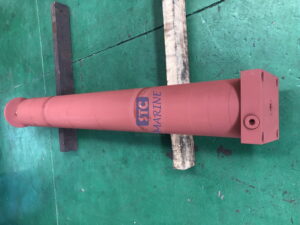
A grab hydraulic cylinder is a linear hydraulic actuator installed on a grab attachment or integrated into its operating mechanism. It uses pressurized hydraulic oil to move a piston inside a cylinder barrel. The piston is connected to a rod, which transfers the resulting force to a linkage, jaw, shell, or tine assembly. Depending on the grab design, the cylinder may push, pull, or operate through a mechanical linkage to produce the required opening and closing movement.
Unlike a standard hydraulic cylinder used in a stationary machine, a grab hydraulic cylinder often operates in a demanding material-handling environment. It may be exposed to impact, vibration, abrasive dust, moisture, changing loads, and repeated operating cycles. Its design must therefore account not only for hydraulic pressure and output force but also for structural protection, mounting geometry, rod stability, sealing performance, and maintenance accessibility.
The term can refer to different cylinder configurations depending on the equipment. A clamshell grab may use one or more cylinders to move two bucket shells, while an orange-peel grab can use cylinders to control multiple articulated tines. Some grapple buckets use a centrally mounted cylinder to operate a movable upper jaw. The number and arrangement of cylinders are determined by the grab’s mechanical design rather than by one universal configuration.
What Does a Grab Hydraulic Cylinder Do?
The primary function of a grab hydraulic cylinder is to provide controlled linear force for gripping and releasing materials. Its movement is transferred through pins and linkages to the grab’s working components, allowing the operator or control system to manage the attachment during a handling cycle.
Its main functions include:
- Opening the grab: The cylinder moves the jaws, shells, or tines outward to create an opening large enough to collect the target material. The required stroke depends on the grab’s geometry and the opening width needed for the application.
- Closing and gripping materials: Hydraulic pressure drives the cylinder in the opposite direction, bringing the working components together. The resulting gripping force helps retain the material during lifting and transportation.
- Maintaining load control: The cylinder and hydraulic circuit help keep the grab in its intended position while the equipment handles a load. Properly designed valves and hydraulic components help prevent unintended movement.
- Supporting repeated operation: In continuous loading and unloading work, the cylinder must complete frequent opening and closing cycles without excessive leakage, overheating, or premature wear.
A critical distinction is that cylinder force is not identical to the final gripping force at the jaws. The mechanical advantage of the linkage, pivot positions, and angle of operation all influence how much of the cylinder’s output reaches the gripping components. A cylinder with a larger bore does not automatically produce a proportionally greater effective gripping force at every point in the operating stroke.
How Does a Grab Hydraulic Cylinder Work?
A grab hydraulic cylinder works by directing pressurized oil into one side of its piston. The pressure difference across the piston creates a force that moves the piston and rod. The rod then drives the grab mechanism through its connecting links or direct mounting points.
Most industrial grab applications use double-acting cylinders because hydraulic pressure is required to control movement in both directions. This arrangement provides powered opening and closing rather than relying entirely on gravity or a spring for the return movement.
A typical operating cycle involves the following stages:
- Opening: The hydraulic control valve directs oil into the appropriate cylinder chamber. The piston moves, retracting or extending the rod according to the linkage design, and the grab opens.
- Positioning: The crane, excavator, or other carrier positions the open grab above the material. The cylinder holds or maintains the required position through the hydraulic circuit.
- Gripping: The control valve reverses the oil flow. The cylinder moves in the opposite direction, causing the jaws or shells to close around the material.
- Lifting and transportation: Once the material is secured, the carrier lifts and moves the grab. The cylinder, linkage, and hydraulic holding arrangement must maintain the required grip throughout this stage.
- Discharging: At the unloading point, the hydraulic circuit commands the grab to open, allowing the material to fall or be released.
The exact direction of rod movement during opening or closing depends on the cylinder mounting and linkage design. Retraction does not always mean opening, and extension does not always mean closing.
For example, a hydraulic orange-peel grab uses several articulated shells to handle scrap, waste, and irregular materials. Its cylinders coordinate the movement of the shells so they can penetrate a material pile, close around the load, and release it at the unloading point.
Where Are Grab Hydraulic Cylinders Used?
Grab hydraulic cylinders are used in equipment that needs to grip and handle materials that cannot be efficiently moved with a conventional bucket or lifting attachment. The cylinder configuration varies according to the type of grab and the characteristics of the load.
- Hydraulic Clamshell Grabs
Hydraulic clamshell grabs typically have two opposing shells that open and close around loose bulk materials. Hydraulic cylinders actuate the shells, making this equipment suitable for loading and unloading coal, sand, gravel, ore, grain, and other bulk cargo. They are commonly used with port cranes, overhead cranes, gantry cranes, and material-handling systems.
- Orange-Peel Grabs
Orange-peel grabs use multiple curved or articulated tines arranged around a central structure. Their hydraulic cylinders control tine movement, allowing the grab to collect irregular and bulky materials such as scrap steel, metal waste, rocks, and mixed refuse. The number of tines and their geometry influence penetration, closing behavior, and material retention.
- Excavator Grapples
Excavator grapples use hydraulic cylinders to move one or more jaws or gripping arms. They are widely applied in forestry, demolition, recycling, construction, and land clearing. Depending on the attachment, the cylinder may control a single movable jaw or a more complex gripping mechanism.
- Timber and Log Grabs
Timber grabs use hydraulic cylinders to close gripping arms around logs, branches, or bundles of wood. Smooth and controlled movement is important because the grab must secure loads of different sizes without unnecessarily damaging the material or placing excessive stress on the attachment.
These applications are reflected in equipment ranges from manufacturers such as Cromex, which lists clamshell, polyp, timber, and sorting grab designs, and BECO, which documents hydraulic clamshell and orange-peel configurations.
Main Components of a Grab Hydraulic Cylinder
Although the external structure varies by manufacturer and application, most grab hydraulic cylinders contain several core components. Each part contributes to force transmission, sealing, guidance, or protection.
| Component | Main function | Important design consideration |
| Cylinder barrel | Houses the piston and contains hydraulic pressure | Material strength, bore accuracy, and internal surface finish |
| Piston | Separates the two pressure chambers and transfers hydraulic force | Wear resistance and sealing compatibility |
| Piston rod | Transfers linear force to the grab mechanism | Strength, surface hardness, corrosion resistance, and buckling resistance |
| Rod seal and piston seal | Limit internal and external oil leakage | Compatibility with pressure, temperature, and hydraulic fluid |
| Guide bush | Supports and guides the piston rod | Wear resistance and ability to manage expected side loads |
| End caps and ports | Close the cylinder and connect it to the hydraulic circuit | Pressure rating, connection integrity, and serviceability |
| Mounting pins or bearings | Connect the cylinder to the grab structure | Correct alignment, load transfer, and resistance to wear |
The cylinder barrel and piston must maintain reliable pressure containment, while the seals prevent oil from bypassing the piston or escaping around the rod. The rod and mounting components transfer the force to the grab mechanism, so their dimensions and strength must match the loads expected during operation.
For heavy-duty grabs, protective covers, recessed hydraulic connections, and robust mounting arrangements can help reduce damage from external impacts and debris. Some specialized grab designs also incorporate cylinder-specific hydraulic damping or connection layouts to reduce hose exposure and mechanical impact at the end of the stroke.
Key Factors When Selecting a Grab Hydraulic Cylinder
Choosing a suitable grab hydraulic cylinder involves more than matching the cylinder’s bore or overall length. The cylinder must be compatible with the attachment’s mechanical structure and the hydraulic system of the carrier. An unsuitable selection can lead to insufficient gripping force, slow operation, unstable movement, excessive heat, or premature component failure.
- Bore Diameter and Operating Pressure
The cylinder bore determines the piston area, which directly affects the theoretical force generated at a given hydraulic pressure. For a simplified calculation:
F=P×A
Where:
- F is the theoretical hydraulic force.
- P is the pressure acting on the piston.
- A is the effective piston area.
For extension, the effective area is generally the full piston area. For retraction, the piston rod reduces the effective pressure area, so the available force is usually lower at the same pressure. Actual force at the grab jaws also depends on mechanical leverage, friction, and operating geometry.
- Stroke Length and Installation Dimensions
Stroke length determines how far the piston rod can travel. It must provide enough movement to achieve the required grab opening and closing range without forcing the linkage beyond its designed limits. The closed and open mounting dimensions, pin-center distances, and clearance around the cylinder should all be checked before replacement or customization.
- Load Conditions and Rod Stability
Grab cylinders can experience changing loads as the jaws penetrate material, close around an object, and hold it during lifting. If the cylinder operates under compression, a long extended rod may be vulnerable to buckling. ISO/TS 13725:2021 provides a method for evaluating hydraulic cylinder buckling load and specifically considers mounting geometry and possible off-axis loading.
- Sealing and Environmental Protection
Dust, moisture, abrasive particles, and temperature variations can shorten seal life and damage exposed rod surfaces. A suitable cylinder should use seals compatible with the hydraulic fluid and operating temperature, along with appropriate rod protection and corrosion resistance for the working environment.
- Hydraulic Flow and Operating Speed
Cylinder speed is influenced by the hydraulic flow rate and the effective piston area. A cylinder that is too large for the available flow may operate slowly, while an unsuitable valve arrangement can cause jerky movement or poor control. The cylinder should therefore be selected as part of the complete hydraulic system, not as an isolated component.
The following table summarizes the main selection checks for different grab applications.
| Selection factor | What to verify | Why it matters |
| Grab type | Clamshell, orange-peel, timber, or excavator grapple | Determines the movement and mounting arrangement |
| Required force | Working pressure, bore, rod diameter, and linkage ratio | Ensures sufficient gripping performance |
| Stroke | Required jaw travel and open/closed dimensions | Provides the correct operating range |
| Load and mounting | Compression, tension, pin positions, and side loading | Reduces structural stress and buckling risk |
| Operating environment | Dust, water, abrasion, and temperature | Influences material, coating, and seal selection |
| Hydraulic system | Flow rate, pressure, valves, and hose connections | Supports stable movement and system compatibility |
| Maintenance | Seal replacement, inspection access, and spare parts | Helps reduce downtime and lifecycle costs |
Common Problems and Maintenance of Grab Hydraulic Cylinders
Grab hydraulic cylinders work under repetitive and often harsh conditions. Regular inspection is important because small hydraulic or mechanical problems can affect the entire grab’s performance.
External oil leakage is one of the most visible warning signs. It may result from worn rod seals, damaged sealing surfaces, loose connections, or contamination. Internal leakage can be harder to identify: worn piston seals may allow oil to bypass the piston, reducing force and causing the grab to drift or struggle to maintain its position.
Other common problems include scratched or corroded piston rods, damaged hoses, loose mounting pins, worn bushings, and abnormal movement caused by air in the hydraulic circuit or inconsistent oil supply. A bent rod or misaligned mounting arrangement can also increase seal wear and create uneven loading. Repeated operation against mechanical end stops may generate impact loads that damage the cylinder or the grab structure.
A practical maintenance program should include:
- Check for leakage: Inspect the rod, seals, ports, hoses, and connections for visible oil loss.
- Inspect the piston rod: Look for scratches, corrosion, dents, or signs of bending that could damage the seals.
- Monitor operating behavior: Pay attention to slow movement, uneven opening and closing, drifting, unusual noise, or reduced gripping performance.
- Examine mounting components: Check pins, bearings, bushings, and brackets for looseness, deformation, or excessive wear.
- Maintain hydraulic oil quality: Follow the equipment manufacturer’s recommendations for filtration, fluid condition, and replacement intervals.
- Inspect the complete hydraulic circuit: Check valves, hoses, fittings, and pressure settings rather than assuming every operating problem originates in the cylinder.
Maintenance intervals should be based on the equipment manufacturer’s instructions, duty cycle, and actual operating environment. Before inspection or repair, the attachment must be safely supported, hydraulic pressure released according to the service procedure, and the machine isolated to prevent unintended movement.

How to Improve the Service Life of a Grab Hydraulic Cylinder?
Long service life depends on correct cylinder selection, proper installation, suitable hydraulic conditions, and consistent maintenance. Even a well-manufactured cylinder can fail prematurely if it is exposed to excessive side loading, contaminated oil, repeated impact, or operation outside its specified pressure and stroke limits.
First, ensure that the cylinder mounting points align correctly with the grab linkage. A cylinder should primarily transmit force along its intended axis; it should not be used as a structural support for loads that the attachment frame or linkage is designed to carry. Second, verify that the hydraulic system supplies clean oil at the specified pressure and flow rate. Contamination can accelerate wear in seals, piston surfaces, valves, and other hydraulic components.
It is also important to avoid forcing the grab to handle loads beyond the rated capacity of the attachment or carrier. Excessive gripping resistance, side pulling, and repeated impact can place abnormal loads on the cylinder and its mounting structure. Equipment operating manuals commonly emphasize observing attachment and carrier load limits and avoiding unintended side loading.
Finally, use replacement cylinders that match the original installation dimensions and operating requirements. Comparing only bore diameter and stroke is insufficient; rod diameter, mounting style, port configuration, pressure rating, seal materials, and extended and retracted lengths should also be checked. For a custom or heavily modified grab, engineering verification of force, linkage geometry, and rod stability is preferable to selecting a cylinder by appearance alone.
Frequently Asked Questions About Grab Hydraulic Cylinders
- What is a grab hydraulic cylinder used for?
A grab hydraulic cylinder controls the opening and closing movement of a hydraulic grab, grapple, or grab bucket. It generates the linear force needed to grip, hold, and release materials during handling operations.
- How does a hydraulic grab cylinder work?
It uses pressurized hydraulic oil to move a piston and piston rod inside the cylinder. The rod transfers this movement through a linkage to open or close the grab’s jaws, shells, or tines.
- What type of hydraulic cylinder is used in a grab?
Double-acting hydraulic cylinders are commonly used because they provide powered movement in both opening and closing directions. The required configuration depends on the grab structure, operating pressure, stroke, and load conditions.
- What materials can a hydraulic grab handle?
Depending on its design, a hydraulic grab can handle coal, sand, gravel, ore, scrap metal, timber, construction waste, and other bulk or irregular materials. The grab structure, cylinder force, and attachment capacity must be matched to the material and working conditions.
- How do you calculate the force of a grab hydraulic cylinder?
The theoretical cylinder force is calculated by multiplying hydraulic pressure by the effective piston area. However, the actual gripping force at the jaws also depends on the linkage ratio, pivot positions, friction, and cylinder operating angle.
- Why does a grab hydraulic cylinder lose gripping force?
Common causes include insufficient hydraulic pressure, internal seal leakage, damaged piston rods, worn linkage components, and incorrect hydraulic valve operation. Checking both the cylinder and the complete hydraulic circuit is necessary to identify the underlying problem.
Conclusion
A grab hydraulic cylinder is a key actuator in hydraulic material-handling equipment. It converts hydraulic energy into controlled linear movement, allowing clamshell grabs, orange-peel grabs, excavator grapples, and timber attachments to grip, transport, and release materials efficiently. Its performance directly influences gripping capability, operating speed, load control, and equipment reliability.
For equipment manufacturers and operators, selecting the right cylinder means evaluating more than bore diameter and stroke length. Hydraulic pressure, available flow, rod stability, mounting geometry, sealing performance, environmental conditions, and maintenance requirements must all be considered. A properly matched and maintained grab hydraulic cylinder helps reduce unplanned downtime, improve handling consistency, and support reliable long-term operation.