
Article Summary: A hydraulic jack consists of a pressure-generating pump, a hydraulic fluid reservoir, check valves, a load-bearing cylinder and ram, a release valve, and sealing components that control the movement of fluid and prevent leakage. In marine applications, a hatch cover hydraulic jack is usually part of a larger hatch cover operating system comprising hydraulic power units, control valves, pipelines and cylinders that work together to lift, fold, open, close or position heavy hatch cover panels. Useful references for understanding these components and their operating principles include The Standard Club’s A Master’s Guide to Hatch Cover Maintenance and the Canadian government’s Hydraulic Systems technical publication.
What Is a Hydraulic Jack?
A hydraulic jack is a mechanical lifting device that uses pressurised liquid to generate a significant lifting force. It operates based on Pascal’s law, which states that pressure applied to a confined fluid is transmitted throughout the fluid. This means that a relatively small input force can produce a much larger output force when acting on a larger piston area. This principle makes hydraulic jacks ideal for lifting heavy machinery, structural components, vehicles, and industrial equipment.
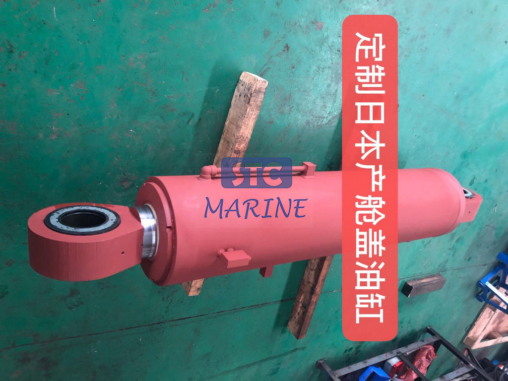
In marine engineering, hydraulic lifting equipment plays an important role in operating hatch covers. A hatch cover hydraulic jack or hydraulic lifting cylinder provides the force needed to raise or position hatch cover panels, depending on the vessel’s design. Some systems use external hydraulic cylinders to open and close covers, while others use hydraulic jacks to lift panels before moving them with wheels, chains, or other mechanical arrangements. The exact configuration depends on the type of hatch cover and its operating mechanism.
It is important to distinguish between an individual hydraulic jack and the complete hatch cover hydraulic system. While the jack or cylinder converts hydraulic pressure into mechanical movement, the complete system also incorporates a power unit, a pump, control valves, an oil tank, piping, hoses, and safety devices. All these parts must work together to provide controlled movement and hold the hatch cover in its intended position.
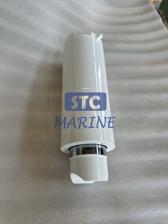
What Are the Main Components of a Hydraulic Jack?
The design of a hydraulic jack depends on whether it is manually operated or powered by a hydraulic power unit, and whether it is single-acting or double-acting. However, most hydraulic lifting arrangements share several essential components. The following sections explain the function of these components and how they contribute to safe and reliable lifting.
- Hydraulic Cylinder Barrel
The cylinder barrel is the main pressure-containing component of a hydraulic cylinder. It contains the internal chamber in which hydraulic oil acts on the piston or plunger to generate linear movement. The barrel must be able to withstand the system’s working pressure while maintaining an accurate internal surface finish because excessive wear, corrosion, or dimensional distortion can damage seals and affect the cylinder’s performance.
In the case of a hatch cover hydraulic jack, the barrel is typically made of high-strength steel, chosen based on the required pressure, load, stroke, and marine operating environment. Its dimensions are determined by the cylinder bore, wall thickness, and structural design. In marine service, protective coatings and suitable material specifications are important because the equipment is exposed to humidity, saltwater spray, and changing environmental conditions.
- Piston and Piston Rod
The piston separates the internal cylinder chambers and is pushed by the pressurised hydraulic oil. When oil enters the correct chamber, the pressure acts on the piston’s effective area and pushes it along the cylinder barrel. The piston rod then transfers this linear force to an external mechanism, such as a hatch cover panel, lifting linkage or connecting bracket.
The piston rod must be strong and hard-wearing enough to resist bending, friction, and repeated loading. Its exposed surface is usually precision-finished and protected against corrosion since damage to the rod can quickly wear the rod seal and cause hydraulic leakage. In hatch cover applications, the rod end connection must also be compatible with the cover’s movement geometry to prevent unintended side loads on the cylinder.
- Hydraulic Pump
The hydraulic pump provides the oil flow required to operate the jack. In a manually operated jack, a hand lever drives a small pump piston or plunger. In a marine hatch cover system, the pump is typically integrated into a hydraulic power unit and driven by an electric motor or another suitable power source. The pump moves hydraulic fluid from the reservoir into the pressure circuit, enabling the cylinder to extend or retract.
Various pump designs are available, including gear, vane, and piston pumps. The most suitable type depends on the required pressure, flow rate, operating duty, efficiency, and maintenance requirements of the system. For hatch cover operation, the pump’s capacity must match the number of cylinders or motors that may operate simultaneously, as well as the required opening or closing speed. Insufficient flow from a pump can result in slow or inconsistent movement, while an incorrectly selected pressure rating can compromise system reliability.
- Hydraulic Fluid Reservoir
The reservoir, also known as the hydraulic oil tank, stores the working fluid required by the hydraulic system. It supplies oil to the pump and compensates for changes in fluid volume when cylinders extend and retract. A properly designed reservoir allows entrapped air to separate from the oil and enables heat to dissipate before the fluid returns to the circuit.
In a hatch cover hydraulic power unit, the tank may include a level indicator, a filling connection, a breather and a drain plug, as well as internal arrangements that help to reduce contamination and turbulence. The capacity of the reservoir should account for the total oil volume required by the cylinders and pipework, as well as the operating conditions specified by the system designer. It is essential to regularly check the oil level, cleanliness, and condition because contaminated or unsuitable hydraulic oil can accelerate wear in pumps, valves, and cylinder seals.
- Check Valves
Check valves control the direction of hydraulic fluid flow and prevent reverse flow. In a conventional, manually operated hydraulic jack, the inlet and outlet check valves work together during the pumping cycle: one valve allows oil to enter the pump chamber and the other allows pressurised oil to move towards the lifting cylinder. When the pump lever is released, the valves prevent the pressurised oil from flowing back into the reservoir.
The valve arrangement used in marine hydraulic circuits depends on the cylinder type and operating design. For example, pilot-operated check valves can help to hold a cylinder in position by preventing uncontrolled return flow until the appropriate release pressure is applied. This is particularly important when a heavy hatch cover must remain stable during an operating sequence. However, check valves should not be used as a substitute for the mechanical supports or locking devices specified for maintenance and safety purposes.
- Release Valve and Directional Control Valve
The release valve controls the return of pressurised oil from the jack to the reservoir, enabling the lifting ram to retract. In a simple hydraulic jack, opening the release valve creates a return path for the oil, enabling the load to descend in a controlled manner. The valve must provide suitable flow control, as releasing pressure too quickly can cause sudden movement.
In a Powered Hatch Cover Hydraulic Jack system, directional control valves play a more significant role. They direct oil to the required cylinder port to extend or retract the piston, while other valves may regulate flow, pressure, or load holding. Marine hatch cover control valve groups may include directional, balance, relief, throttle, check, and pressure gauge valves. These components coordinate the movement of the hatch cover and help prevent it from being operated unintentionally.
- Hydraulic Seals and O-Rings
Seals prevent hydraulic oil from escaping between moving and stationary components. Common sealing elements include piston seals, rod seals, O-rings, backup rings, and wiper seals. Piston seals maintain separation between cylinder chambers, while rod seals prevent oil leakage along the piston rod. Wiper seals help to prevent dust, water, and other contaminants from entering the cylinder when the rod is in motion.
The material of the seal must be compatible with the hydraulic fluid, working temperature, pressure, and operating environment. In marine applications, seal degradation can be accelerated by contamination, corrosion, high temperatures, incorrect installation, or prolonged operation under unsuitable conditions. Therefore, leakage should be investigated rather than treated as a minor cosmetic issue, since fluid loss can reduce performance and create slip hazards on deck.
- Cylinder End Caps, Mounting Points, and Bearings
Cylinder end caps close off the ends of the barrel, providing the necessary interfaces to retain the internal components and connect the cylinder to the external structure. Depending on the design, one end may incorporate the rod gland, while the other end may provide the base connection. Mounting points, pins, clevises, spherical bearings, or rod-end bearings transfer the cylinder’s force to the hatch cover mechanism.
These connections are important because hatch covers move through defined arcs or linked mechanical paths rather than following a perfectly straight line. Suitable bearings and mounting arrangements help to accommodate the required movement and reduce unwanted bending loads on the piston rod. Incorrect alignment can result in uneven seal wear, scoring of the rod, premature bearing failure, or structural damage around the mounting brackets.

Additional Components in a Hatch Cover Hydraulic System
A hydraulic jack used on a ship rarely operates as an isolated unit. It is connected to a wider hydraulic circuit that supplies power, regulates pressure, directs oil, and coordinates the movement of the hatch cover. Understanding these supporting components is important when selecting replacement parts, diagnosing operating problems, or planning maintenance.
- Hydraulic Power Unit (HPU)
The hydraulic power unit is the central source of hydraulic energy for many powered hatch cover systems. It typically incorporates an electric motor, a hydraulic pump, a reservoir, filters, pressure-control devices, and related instruments. When the motor drives the pump, hydraulic oil is drawn from the tank and delivered into the system under pressure. Depending on the vessel’s design and operating sequence, the HPU may supply one cylinder or several actuators.
The HPU must be selected according to the required pressure, flow rate, duty cycle, and number of actuators. Some installations also use oil coolers or accumulators to manage heat and pressure fluctuations. Additionally, the HPU should provide suitable access for checking the oil level, changing the filters, inspecting the connections, and carrying out routine maintenance. The Standard Club’s A Master’s Guide to Hatch Cover Maintenance highlights pump units, cylinders, motors, and control valves as key components of hatch cover hydraulic systems that demand thorough inspection and maintenance.
- Pressure Relief and Load-Control Valves
Pressure relief valves protect the hydraulic circuit against excessive pressure. If the system pressure rises above the specified setting, the relief valve opens and diverts oil to the reservoir or another low-pressure outlet. This helps to protect the pump, cylinder, hoses, pipes, and other pressure-containing components from overload. The relief setting must adhere to the specifications of the system manufacturer; increasing it without engineering approval can expose the equipment to unsafe loads.
Load-control valves serve a different but related purpose. Depending on the circuit design, counterbalance valves or other load-holding arrangements can regulate movement when a cylinder is supporting or controlling a heavy load. They help prevent an actuator from moving too quickly under an external force, such as the weight of a hatch cover. Selecting and adjusting the correct valve is essential because the load, geometry, and movement characteristics vary between hatch cover designs.
- Hydraulic Pipes and Flexible Hoses
Hydraulic pipes and hoses are used to transport oil between the power unit, control valves, and cylinders. Rigid pipes are typically employed for fixed sections of the circuit, whereas flexible hoses allow for movement and vibration, and connect components that cannot be joined by rigid pipework. Both must be rated for the system’s maximum working pressure, temperature, fluid type, and operating environment.
In marine installations, particular attention should be given to pipe supports, hose routing, fittings, and protective arrangements. Excessive vibration, abrasion against surrounding structures, corrosion, sharp bends, and poorly secured connections can lead to leaks or hose failure. Inspection should cover the entire hydraulic circuit, not just the visible connections near the jack. Any replacement hose or pipe must meet the specified pressure and dimensional requirements.
- Filters and Pressure Gauges
Filters remove solid contaminants from hydraulic oil to prevent damage to precision components. Depending on their design, filters can be installed on the suction, pressure, or return side of a hydraulic circuit. Their location and filtration rating must comply with the manufacturer’s specifications for the system, as an unsuitable filter may restrict the flow of oil or fail to provide adequate protection.
Pressure gauges and sensors enable operators and maintenance personnel to monitor system pressure during operation and testing. Abnormal readings may indicate a problem with the pump, a blocked filter, an internal cylinder leak, an incorrect valve setting, or an excessive load. Pressure readings should always be interpreted alongside the vessel’s hydraulic diagram and operating instructions. A gauge reading alone cannot confirm whether a hatch cover is mechanically secured or safe to work beneath.
- Control Panel and Operating Devices
The control panel is the interface through which authorised personnel operate the hatch cover system. Depending on the vessel, it may include push buttons, selector switches, indicator lights, emergency stop functions and status signals. Electrical controls activate solenoid valves, motor starters or other devices that govern hydraulic operation.
The control arrangement should clearly indicate which hatch cover or actuator is being operated and whether the system is in the intended operating mode. Where fitted, interlocks and alarms help reduce the risk of incorrect operation. Nevertheless, operators must adhere to the ship-specific procedure and maintain communication with personnel in the operating area, especially when panels are in motion or visibility is limited.
Hydraulic Jack Components and Their Functions at a Glance
The following table summarizes the main components of an individual hydraulic jack and the wider hatch cover hydraulic installation. This distinction helps buyers and maintenance teams identify whether a replacement is needed for the cylinder itself or for a supporting system component.
| Component | Main function | Typical relevance to hatch cover operation |
| Cylinder barrel | Contains pressurized hydraulic oil | Provides the pressure chamber for lifting or moving the cover |
| Piston and piston rod | Converts hydraulic pressure into linear force and movement | Transfers force to the hatch cover or its linkage |
| Hydraulic pump | Supplies pressurized oil flow | Powers cylinder extension and retraction |
| Oil reservoir | Stores hydraulic fluid | Provides the system’s oil supply and return volume |
| Check valve | Controls one-way fluid flow | Helps prevent reverse flow and unwanted movement |
| Release valve | Allows oil to return from the actuator | Controls lowering or pressure release |
| Directional control valve | Directs oil to the required circuit | Selects the movement direction of the actuator |
| Seals and O-rings | Prevent internal and external leakage | Maintain pressure and protect moving interfaces |
| Hydraulic power unit | Supplies and manages hydraulic power | Provides the operating energy for the system |
| Relief/load-control valve | Limits pressure or regulates loaded movement | Helps protect equipment and control heavy cover movement |
| Pipes and hoses | Carry hydraulic oil through the circuit | Connect the power unit, valves, and cylinders |
| Filters and gauges | Maintain fluid cleanliness and monitor pressure | Support reliable operation and fault diagnosis |
How Does a Hatch Cover Hydraulic Jack Work?
A hatch cover hydraulic jack works by converting hydraulic energy into mechanical force. When the operator activates the system, the electric motor drives the hydraulic pump, drawing oil from the reservoir and sending it into the pressure circuit. The directional control valve then directs the oil to the appropriate cylinder port. As pressurised oil enters the cylinder chamber, it acts on the piston’s effective area, pushing the piston and rod outwards and producing the movement required by the hatch cover mechanism.
The force generated by a hydraulic cylinder is determined by the pressure acting on its effective piston area. In simplified terms:
F=P×A
Where:
- F = theoretical hydraulic force
- P = hydraulic pressure
- A= effective piston area
This relationship explains why hydraulic systems can move heavy structures with relatively compact actuators. Actual usable force is affected by friction, pressure losses, rod-side area in a double-acting cylinder, mechanical linkage geometry, and system efficiency. The cylinder bore, rod diameter, operating pressure, and stroke must therefore be calculated for the specific hatch cover design rather than selected from load capacity alone.
When the hatch cover reaches its required position, the hydraulic circuit may use load-holding valves or other designed arrangements to control the actuator. To reverse the movement, the control valve changes the oil flow path so that the cylinder retracts or moves in the opposite direction. The actual sequence varies with folding, rolling, lift-and-roll, and other hatch cover arrangements; it should always be taken from the vessel’s approved hydraulic diagram and manufacturer’s instructions.
Common Hydraulic Jack Types Used in Marine Applications
Not all hydraulic jacks are designed for the same lifting arrangement. The cylinder type, return mechanism, mounting configuration, and operating pressure should match the hatch cover’s weight and movement requirements.
- Single-acting hydraulic cylinder: Hydraulic pressure moves the piston in one direction, while retraction occurs through an external load, spring, or another mechanical arrangement. This design may be suitable where the hatch cover mechanism provides a controlled return force.
- Double-acting hydraulic cylinder: Hydraulic pressure is applied alternately to both sides of the piston to extend and retract the rod. It provides powered movement in both directions and is commonly used where controlled opening and closing are required.
- Telescopic hydraulic cylinder: Multiple nested stages extend in sequence to provide a relatively long stroke from a compact retracted length. It is useful in applications where installation space is limited but substantial extension is needed, subject to the equipment’s load and stability limits.
- Heavy-duty lifting cylinder: This type is designed for high-force lifting applications and may use a large piston area, reinforced construction, and specialized mounting arrangements. Its suitability depends on the calculated load, operating pressure, stroke, and duty cycle.
| Hydraulic cylinder type | Movement principle | Key selection consideration |
| Single-acting | Pressure-driven movement in one direction; return by load or spring | Return force and controlled lowering |
| Double-acting | Hydraulic pressure drives extension and retraction | Required force in both directions |
| Telescopic | Nested stages extend to provide a long stroke | Stroke length, stability, and installation space |
| Heavy-duty lifting cylinder | Large effective piston area generates high lifting force | Rated capacity, structural strength, and mounting design |
These categories describe general cylinder arrangements, not interchangeable products. A replacement Hatch Cover Hydraulic Jack should match the original equipment’s dimensions, mounting points, stroke, pressure rating, and operating characteristics. Where the original design is unavailable, engineering review of the hatch cover mechanism and hydraulic circuit is necessary before specifying an alternative.

Maintenance Considerations for Hatch Cover Hydraulic Jacks
Marine hydraulic equipment operates in a demanding environment. Saltwater exposure, humidity, vibration, heavy cyclic loads, and contamination can gradually affect cylinder surfaces, seals, hoses, valves, and hydraulic oil. A maintenance program should therefore cover the complete operating system rather than focusing only on the visible cylinder.
Key inspection areas include:
- Cylinder and rod condition: Check for oil leakage, corrosion, pitting, scratches, abnormal wear, and damage around mounting points. A damaged rod surface can quickly deteriorate the rod seal.
- Hydraulic oil quality: Monitor oil level, cleanliness, and viscosity according to the manufacturer’s requirements. Water or solid contamination can affect pump and valve performance.
- Hoses and pipework: Inspect for cracks, abrasion, corrosion, loose fittings, deformation, and leakage. Replace damaged components with correctly rated parts.
- Valves and operating pressure: Check for abnormal pressure readings, sticking valves, uncontrolled movement, or failure to hold the intended position.
- Filters and power unit: Inspect the reservoir, filter condition, pump operation, motor, and other HPU components in accordance with the maintenance schedule.
- Mechanical connections: Examine pins, bearings, brackets, and linkage alignment for wear or deformation that could impose side loads on the cylinder.
The Standard Club’s ‘A Master’s Guide to Hatch Cover Maintenance’ emphasises the importance of inspecting hydraulic cylinders, motors, control valves, and power units, as well as paying attention to oil cleanliness and leakage. The guide also highlights the hazards associated with operating high-pressure hydraulics alongside heavy, moving hatch covers. Before working on or beneath a raised cover, maintenance personnel should follow the vessel’s safety management procedures, isolate hydraulic and electrical energy, and use the designed mechanical supports. Never rely solely on hydraulic pressure to support a hatch cover during maintenance.
Frequently Asked Questions About Hatch Cover Hydraulic Jacks
- What are the main components of a hydraulic jack?
The main components are the hydraulic pump, oil reservoir, cylinder, piston, piston rod, check valves, release valve, and seals. A powered marine system also includes a hydraulic power unit, control valves, filters, and connecting pipes or hoses.
- What is a Hatch Cover Hydraulic Jack used for?
A Hatch Cover Hydraulic Jack provides hydraulic force to lift, position, or move hatch cover panels, depending on the vessel’s design. It may operate as part of a larger system that controls hatch cover opening and closing.
- What is the difference between a hydraulic jack and a hydraulic cylinder?
A hydraulic jack is generally a lifting device that uses hydraulic pressure to raise a load, often through an integrated pump and release mechanism. A hydraulic cylinder is an actuator that converts hydraulic pressure into linear movement and can be connected to an external hydraulic power unit.
- What type of hydraulic cylinder is used for ship hatch covers?
Single-acting and double-acting cylinders are both used in marine applications, depending on the hatch cover mechanism. The selection depends on the required movement, lifting force, stroke, return arrangement, and system design.
- Why does a hatch cover hydraulic jack leak oil?
Common causes include worn piston or rod seals, a scratched piston rod, damaged hoses, loose fittings, and corrosion around sealing surfaces. The source of leakage should be identified and repaired using the specified replacement parts and maintenance procedures.
- How do you choose a replacement hatch cover hydraulic jack?
Check the original cylinder’s rated force, working pressure, stroke, bore, rod diameter, mounting dimensions, and operating type. Also confirm material specifications, seal compatibility, and the vessel’s hydraulic circuit requirements before ordering a replacement.
Conclusion
The main components of a hydraulic jack are the cylinder barrel, piston, piston rod, pump, reservoir, check valves, release valves, and sealing elements. In marine applications, a hatch cover hydraulic jack also relies on supporting equipment such as a hydraulic power unit, pressure relief valves, load-control devices, filters, hoses, pipes, and operating controls.
Understanding how these components work together helps shipowners, marine equipment manufacturers, and maintenance teams to select suitable equipment and identify potential faults. The most important considerations when purchasing or replacing a hatch cover hydraulic jack are rated force, working pressure, stroke length, mounting dimensions, cylinder type, material compatibility, and operating conditions. Matching these specifications to the vessel’s original design is essential for reliable operation of the hatch cover and long-term service.