

Article Summary: To select the right grab hydraulic cylinder, you need to match its pushing and pulling force, stroke length, working pressure, mounting geometry, and duty cycle to the actual operating loads of the grab. While hydraulic design principles described in engineering references such as Machinery’s Handbook and ISO 6020/6022 cylinder standards provide a sound basis for sizing, grab applications also require careful consideration of impact loads, rod buckling, synchronisation, and corrosion protection in demanding marine or bulk-handling environments.
What Is a Grab Hydraulic Cylinder?
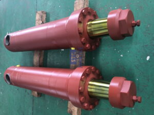
A grab hydraulic cylinder is a type of hydraulic actuator that is used to open, close, position, or operate a grab mechanism for handling bulk materials. Depending on the design of the equipment, it can be installed on a hydraulic grab, a clamshell grab, a material-handling attachment, or other grab-type lifting equipment used in ports, on ships, in recycling facilities, on construction sites, and in industrial material-handling operations. By converting hydraulic pressure into linear motion, the cylinder provides the force needed to move the grab’s linkage and jaws against the resistance of the material being handled.
While its operating principle is similar to that of a standard industrial hydraulic cylinder, a grab hydraulic cylinder often operates under more demanding loading conditions. It may encounter sudden resistance when the jaws penetrate compacted cargo, repeated impacts during loading and unloading, vibration during crane movement, and changing leverage as the grab opens and closes. For marine equipment in particular, salt spray, humidity, temperature fluctuations and long periods of outdoor exposure introduce additional requirements for rod protection, sealing and coating, as well as maintenance.
Therefore, the right cylinder is not necessarily the largest model available or the one with the highest nominal pressure rating. Rather, it is the cylinder that provides the required force throughout the complete operating cycle, fits the grab’s linkage geometry, can withstand the actual structural loads, and operates within the hydraulic system’s pressure and flow limits. Selecting a cylinder based solely on bore diameter or the external appearance of an existing cylinder can result in important differences in rod strength, stroke, pin dimensions, and allowable loading being overlooked.
Identify the Grab Type and Operating Conditions First
Before calculating the dimensions of the cylinder, establish how the grab operates and what the actuator must accomplish. Different grab mechanisms transfer cylinder force through various combinations of levers, links, hinges, and jaw structures. Therefore, the force required at the cylinder rod can vary significantly, even between grabs with similar capacities. For example, a clamshell grab designed for loose grain may experience a different resistance profile to one designed for dense mineral material or scrap.
Start by documenting the type of equipment, the rated grab capacity, the material density, the expected working cycle, and the movement that the cylinder controls. Confirm whether the cylinder opens and closes the jaws directly or drives an intermediate linkage. If the grab has two or more cylinders, establish whether they operate together, independently, or via a hydraulic synchronisation arrangement. These details influence the force calculation, the required stroke and the control strategy.
The most useful information comes from the manufacturer’s drawings and load data rather than from an estimate based on machine size alone. Where drawings are unavailable, carefully measure the existing installation and record the pin-to-pin dimensions with the cylinder fully retracted and extended. Also record the mounting type, the rod-end connection, and the hydraulic port arrangement. These measurements are particularly important for replacement cylinders because even a small change in closed length or stroke can prevent the grab from closing completely or force the mechanism beyond its intended travel.
Calculate the Required Force and Select the Cylinder Bore
The first major sizing decision is the force the grab hydraulic cylinder must deliver at the operating pressure available at the cylinder. The basic relationship is:
F=P✖ A
where F is theoretical cylinder force, P is hydraulic pressure, and A is the effective piston area. During extension, pressure acts on the full piston area; during retraction, the piston rod reduces the effective area, so the pulling force is lower at the same pressure. This distinction is critical when the grab relies on cylinder retraction to close or open its jaws.
For extension, the theoretical force is calculated using A = πD²/4, where D is the cylinder bore. For retraction, the effective area is A = π(D² – d²)/4, where d is the piston rod diameter. These formulas provide a starting point, not a complete design approval: pressure losses through valves and hoses, back pressure, friction, mechanical efficiency, and transient loads affect the force available in actual service. Hydraulic cylinder sizing references consistently emphasize calculating force from the real operating pressure and effective area rather than choosing a bore by visual comparison alone.
A practical selection process is to determine the maximum force needed at the cylinder rod, calculate the required effective area using the pressure available during movement, and then select an appropriate standard or engineered bore size. The calculation must reflect the linkage geometry: the force needed at the grab jaws is not automatically equal to the force needed at the cylinder. As the linkage angle changes through the stroke, its mechanical advantage changes too, meaning that the most demanding point may occur near one end of travel rather than at the middle.
Do not simply add an arbitrary safety percentage and assume the design is complete. Instead, identify credible peak loads, pressure spikes, impact conditions, and the equipment manufacturer’s design requirements, then apply suitable engineering allowances. The cylinder, pins, brackets, grab linkage, hoses, valves, and supporting structure must all be capable of handling the resulting load case.
Choose the Correct Stroke Length and Installation Dimensions
The grab’s movement geometry determines the required stroke length, but it also affects how far the piston rod travels. If the stroke is too short, the jaws may not open or close fully, which reduces handling efficiency. Conversely, if the stroke is too long, the cylinder may bottom out before the mechanism reaches its designed limit. This can result in interference with surrounding components or impose damaging loads on pins and linkage parts.
Therefore, check both the retracted and extended lengths, not just the nominal stroke. For a pin-mounted cylinder, the centre-to-centre distance between the mounting pins is often essential for confirming the fit. Also verify the pin diameter, clevis width, mounting orientation, articulation range, port position, hose clearance, and the space required for rod movement. Spherical bearings or other articulating connections may be necessary where the mechanism changes angle during operation, but these should not be used as a substitute for correct alignment.
If the cylinder is being replaced, the original stroke and mounting dimensions can be used as a reference, but should be checked against the current condition of the grab. Worn pins, deformed brackets, altered linkage geometry, or previous non-standard replacements can render the existing cylinder an unreliable design template. Always confirm the required motion against the equipment drawing or conduct a mechanical inspection before finalising the specification.
Select the Piston Rod, Pressure Rating, and Operating Speed
Bore diameter is just one factor in cylinder sizing. The piston rod must also be able to withstand compression, bending, and repeated loading over the full stroke. If the diameter, unsupported length, material properties, and mounting conditions of a long rod are unsuitable, it can buckle when under load. This risk increases when the cylinder is highly extended, or the load is misaligned with the rod axis. Therefore, engineering sizing guidance treats rod buckling as a separate structural check rather than assuming that a cylinder with sufficient hydraulic force is automatically strong enough.
The rated working pressure must match that of the hydraulic circuit, taking into account the pressure expected during normal operation and any foreseeable peaks specified by the equipment design. The system relief valve setting alone does not determine the cylinder’s complete pressure requirements, and a higher-pressure cylinder should not be used to compensate for incorrect load calculations or poor mechanical alignment. Check the ratings of the barrel, end caps, ports, seals, rod, and connections as a complete assembly.
Operating speed is another important consideration for grab performance. Cylinder speed depends on oil flow and the effective piston area; increasing the bore can increase force at a given pressure, but it also increases the oil volume required for a given stroke. If the existing pump and valve system cannot supply sufficient flow, the grab may operate more slowly than expected. Conversely, rapid movement can increase impact and pressure transients when the jaws reach a mechanical limit or encounter a sudden load. Cylinder sizing must therefore balance force, stroke, available flow, and the required cycle time.
| Selection parameter | What to verify | Why it matters for a grab hydraulic cylinder |
| Bore diameter | Required extension force and available working pressure | Determines theoretical pushing force |
| Rod diameter | Retraction force, compression loading, and buckling resistance | Helps the cylinder withstand extended-stroke loads |
| Stroke | Required jaw movement and linkage geometry | Ensures the grab opens and closes through its intended range |
| Working pressure | Normal operating pressure and specified pressure peaks | Protects the cylinder and hydraulic circuit from overload |
| Flow and speed | Pump capacity, valve flow, and target cycle time | Affects grab response and loading productivity |
| Mounting dimensions | Pin centers, pin diameter, clevis width, and articulation | Ensures physical fit and proper alignment |
| Duty cycle | Operating frequency, load variation, and service conditions | Influences heat generation, seal wear, and maintenance needs |
Consider Seals, Materials, and Marine Corrosion Protection
Hydraulic cylinders used in ports and for shipboard cargo handling, for example, may be exposed to salt spray, rain, dust, abrasive particles, and frequent temperature changes. The appropriate corrosion protection depends on the exposure zone and the expected service life of the cylinder. Common considerations include barrel coating, surface treatment of the piston rod, corrosion-resistant fasteners where appropriate, protective finishes, effective rod wipers and seals that are compatible with the hydraulic fluid and operating temperature. Guidance on selecting marine cylinders also emphasises that corrosion protection involves the rod, seals, mounting parts, drainage and installation position, not simply the external paint.
Seals must be selected based on the specific hydraulic fluid, pressure, temperature, contamination level and motion profile. A rod wiper helps prevent water and abrasive debris from entering the cylinder, while appropriate sealing arrangements limit external leakage and maintain pressure. The exact seal material and configuration should be confirmed with the cylinder manufacturer, as selecting a seal based only on a generic temperature range may result in overlooking fluid compatibility, pressure behaviour or the effects of repetitive impact loading.
For demanding applications, ask the supplier to clarify the specified materials, coating system, rod surface finish, seal arrangement and inspection requirements. Consider also how the cylinder will be stored, transported, installed and maintained. Even a well-selected cylinder can experience premature failure if the rod is damaged during handling, if contamination enters the hydraulic circuit, or if corrosion protection is compromised by poor storage and maintenance.
Match the Cylinder to the Grab’s Duty Cycle and Maintenance Requirements
A grab hydraulic cylinder may experience hundreds or thousands of operating cycles over its service life, with load intensity varying according to the material handled and the operator’s working pattern. A cylinder intended for occasional light-duty operation may not be suitable for continuous cargo handling, even if its bore, stroke, and nominal pressure appear adequate. Review expected cycles per hour, operating hours per day, peak loading frequency, and the amount of time the cylinder spends extended under load. These conditions help determine the required durability, sealing performance, inspection intervals, and maintenance strategy.
For equipment operating in dusty or abrasive environments, contamination control is especially important. Damaged rod surfaces, worn wipers, contaminated hydraulic oil, and misaligned mounting points can accelerate seal wear and lead to leakage or uneven movement. Maintenance planning should include regular inspection of the rod surface, cylinder joints, pins, mounting brackets, hydraulic hoses, and signs of external leakage. Any abnormal movement, recurring pressure loss, or visible rod damage should be investigated before it develops into a more serious equipment failure.
When specifying a new or replacement unit, we recommend supplying the grab manufacturer’s drawing, existing cylinder dimensions, hydraulic pressure and flow data, operating conditions, and photographs of the mounting arrangement. STC MARINE can be considered as a supplier contact for marine-related equipment enquiries, but the final cylinder selection should be based on verified application requirements and confirmed technical specifications. A clear technical enquiry helps the supplier assess whether a standard unit is appropriate or whether a custom cylinder is needed.
Common Mistakes When Selecting a Grab Hydraulic Cylinder
Even when a cylinder appears to match the equipment, several recurring mistakes can cause poor performance. The first mistake is selecting a bore based solely on the grab’s rated lifting capacity without calculating the force transmitted through the linkage. The second mistake is checking the extension force but ignoring the lower effective area during retraction. The third mistake is choosing a stroke based on a single measurement while overlooking the full range of linkage movement and the retracted and extended installation lengths.
Another common error is to treat the cylinder as an isolated component. A larger bore can increase oil demand and slow the cycle if pump flow is insufficient. Conversely, an inadequately sized rod can buckle under compression, despite the cylinder producing the required hydraulic force. In marine service, insufficient corrosion protection and unsuitable sealing can also shorten the service life. The most reliable approach is to evaluate the cylinder, hydraulic circuit, mechanical linkage, mounting structure, and working environment as a whole, and have the final design verified by qualified engineering personnel.
Grab Hydraulic Cylinder FAQs
- How do I calculate the force required for a grab hydraulic cylinder?
Calculate the required force from the load acting on the cylinder, the grab linkage geometry, and the actual working pressure. Then check both extension and retraction forces, including relevant losses and peak loading conditions.
- How do I choose the correct bore size for a grab hydraulic cylinder?
Choose a bore that provides the required force at the available working pressure using the effective piston area. Verify the result against standard sizes, rod strength, operating speed, and the cylinder manufacturer’s ratings.
- How do I determine the stroke length of a grab hydraulic cylinder?
Determine the travel required to move the grab through its full designed opening and closing range. Confirm the linkage geometry, retracted and extended pin-to-pin lengths, and mechanical clearances before ordering.
- What causes a grab hydraulic cylinder to fail?
Common causes include excessive pressure, rod buckling, side loading, seal wear, contaminated hydraulic oil, corrosion, and repeated impact loads. Incorrect installation or unsuitable sizing can accelerate these problems and reduce service life.
- Which material and seals are best for a marine grab hydraulic cylinder?
The appropriate materials and seals depend on seawater exposure, hydraulic fluid, operating temperature, pressure, and contamination levels. Specify suitable rod protection, corrosion-resistant finishes, and compatible sealing components based on the actual service environment.
- Can I replace a grab hydraulic cylinder with a standard hydraulic cylinder?
A standard cylinder may be suitable if its force, pressure rating, stroke, mounting dimensions, rod strength, and duty-cycle capability meet the application requirements. A direct dimensional match alone is not sufficient, especially when the grab operates under high impact loads or demanding marine conditions.
Conclusion
Selecting a grab hydraulic cylinder is an engineering decision that requires more than simply matching a bore diameter or copying an existing part number. The correct selection begins with an analysis of the grab’s operating mechanism and load conditions, followed by a verification of the required force, bore diameter, rod diameter, stroke length, pressure, flow rate, mounting geometry, duty cycle, and environmental protection requirements. As each parameter affects the others, evaluating them together is essential for reliable performance.
The best practice for equipment manufacturers, marine operators and maintenance teams is to provide complete technical information when requesting a quotation, and to confirm the final design against the requirements of the equipment manufacturer. This approach helps to avoid issues such as a poor fit, insufficient force, excessive cycle time, premature wear, and preventable downtime, while supporting safer and more dependable material handling operations.