

Quick Answer
A hydraulic cylinder in a grab converts pressurised hydraulic fluid into linear mechanical motion. This motion is then transferred through pins, links, levers, or grab arms to open and close the shells or jaws. This principle adheres to the general rules of hydraulic systems defined by ISO 4413:2010. Hydraulic grab designs use cylinders as actuating elements for handling bulk and irregular materials.
In a typical operating cycle, the hydraulic pump supplies pressurised oil, the control valves direct the oil into one side of the cylinder, the piston and rod move, and the resulting mechanical movement opens or closes the grab. The available cylinder force is mainly determined by hydraulic pressure, while hydraulic flow influences how quickly the cylinder moves.
What Is a Grab Hydraulic Cylinder?
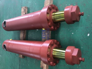
A grab hydraulic cylinder is a type of linear hydraulic actuator that is used to operate a hydraulic grab, grapple, or grab bucket. Its main function is to convert hydraulic energy into linear movement, which is then used to manipulate the grab’s working components. Depending on its mechanical design, the cylinder rod may act directly on a jaw or shell, or it may move a linkage that converts its linear stroke into angular movement.
A conventional hydraulic cylinder consists of a barrel, a piston, a piston rod, seals, guide components, hydraulic ports and mounting connections. When pressurised hydraulic oil enters the cylinder chamber, the resulting pressure acts on the piston surface, producing a force that moves the piston and rod. Oil from the opposite chamber is simultaneously displaced through the hydraulic circuit.
Therefore, the cylinder forms only one part of the complete grab system. A working hydraulic grab may also include a hydraulic power unit, directional control valves, hoses or pipes, pins, bushings, arms, shells, tines, structural frames, and protective components. While the cylinder supplies the linear actuation force, the grab’s mechanical structure determines how this force is converted into gripping movement.
How Does a Grab Hydraulic Cylinder Work?
The working process can be understood as a chain of energy conversion:
Hydraulic pump → pressurized oil → control valve → cylinder chamber → piston movement → piston-rod movement → mechanical linkage → grab opening or closing
When the operator activates the hydraulic control system, pressurized oil is directed toward a selected chamber of the cylinder. Because hydraulic fluid transmits pressure within a confined system, the pressure acts against the effective piston area and produces linear force.
For a double-acting cylinder, hydraulic oil can be supplied to either side of the piston. Supplying oil to the piston side generally extends the rod, while supplying oil to the rod side generally retracts it, although the exact movement depends on the cylinder’s installation orientation and hydraulic circuit.
As the piston rod moves, it pushes or pulls the connected grab mechanism. A linkage may amplify the force or change the movement direction, causing the shells, jaws, or tines to rotate around their pivot points. This allows the grab to close around a load, maintain a gripping force during lifting, and open again when the hydraulic circuit commands the opposite cylinder movement.
Main Components of a Grab Hydraulic Cylinder
The performance of a grab hydraulic cylinder depends on the interaction of several components rather than the cylinder barrel alone.
| Component | Main Function | Importance in a Hydraulic Grab |
| Cylinder barrel | Contains hydraulic fluid and guides piston movement | Provides the main pressure chamber |
| Piston | Separates the two hydraulic chambers | Converts fluid pressure into mechanical force |
| Piston rod | Transfers piston force outside the cylinder | Drives the grab linkage or jaw mechanism |
| Rod seal | Prevents hydraulic oil leakage around the rod | Maintains pressure and prevents contamination |
| Piston seal | Separates the two cylinder chambers | Prevents internal leakage |
| Guide/bushing | Supports and guides the piston rod | Reduces lateral movement and wear |
| Hydraulic ports | Allow oil to enter and leave the cylinder | Connect the actuator to the hydraulic circuit |
| Mounting connection | Connects cylinder to the grab structure | Transfers cylinder force to the mechanical mechanism |
The piston rod and mounting points deserve particular attention in grab applications because a cylinder can experience forces that are not purely axial. Heavy grabs may encounter impact, vibration, uneven loads, and side forces during material handling. Proper structural design, alignment, guides, pins, and bushings help prevent these external loads from being transferred excessively to the cylinder rod or seals.
How Does Hydraulic Pressure Create Grab Force?
The fundamental relationship between hydraulic pressure and cylinder force is:
F = P × A
where F is theoretical hydraulic force, P is hydraulic pressure, and A is the effective piston area.
For example, if a cylinder has a 100 mm piston diameter and operates at 20 MPa, the theoretical extension force is approximately 157 kN, before accounting for friction, seal resistance, pressure losses, and other efficiency factors.
During retraction, the effective area is smaller because the piston rod occupies part of the cylinder area. The theoretical retraction force can therefore be calculated using the annular area:
F = P × π(D² − d²) / 4
where D is the piston diameter, and d is the piston-rod diameter.
This distinction is important when evaluating a grab because cylinder force is not the same as actual gripping force at the material. The final force available at the grab jaw depends on the cylinder force, linkage geometry, pivot locations, leverage ratio, cylinder angle, friction, and the position of the grab mechanism during its closing stroke.
How Does the Cylinder Open and Close the Grab?
The way in which the grab opens and closes depends on its mechanical architecture. In a hydraulic clamshell grab, for instance, the cylinder operates a linkage that causes the two shells to rotate towards or away from each other. Depending on its mounting arrangement, when the cylinder retracts or extends, the connected linkage changes position and moves the shells around their pivots.
In an orange-peel grab, several tines rotate around a central structure to form a gripping envelope. Depending on the grab design, multiple hydraulic cylinders or a coordinated hydraulic mechanism may be used. These systems are commonly used for irregular materials, such as scrap metal, while clamshell configurations are widely associated with free-flowing bulk materials.
Therefore, the mechanical geometry is just as important as the hydraulic cylinder itself. However, a cylinder with a high theoretical force may not produce an equally high gripping force at every point in the jaw’s movement, as the effective leverage changes as the linkage rotates.
Hydraulic Grab Types and Cylinder Arrangements
The design of hydraulic grabs depends on the material being handled, the handling method, the load characteristics and the equipment configuration. Common designs include clamshell grabs, orange-peel grabs, log grabs and other specialised grapples.
A hydraulic clamshell grab typically comprises two shells that close around bulk material. This design is suitable for materials such as coal, sand, grain, ore and other relatively free-flowing products. In contrast, an orange-peel grab uses multiple articulated tines and is particularly useful for handling irregular objects, such as scrap metal.
The number and arrangement of hydraulic cylinders varies. Some grabs use a relatively simple cylinder arrangement, while larger or more specialised designs may use multiple cylinders with coordinated hydraulic control. The most suitable option depends on the required closing force, grab size, material characteristics, available hydraulic pressure, operating cycle, and mechanical geometry.
Hydraulic Pressure vs. Flow: Force vs. Speed
One of the most important concepts in operating a hydraulic grab is understanding the difference between pressure and flow.
Hydraulic pressure is closely related to the force that the cylinder can generate. Increasing the available system pressure can increase the force of the cylinder, provided that it, along with the valves, hoses, fittings, and other components, is designed and rated for the higher pressure.
Hydraulic flow primarily affects how quickly the cylinder extends or retracts. More flow generally produces faster cylinder movement, while less flow produces slower movement. However, actual cylinder speed also depends on piston area, load, hydraulic resistance, valve characteristics, and available pump capacity.
Therefore, simply increasing hydraulic pressure is not an effective solution to every slow-grab issue. If the issue is insufficient flow, a higher pressure setting could put additional strain on the components without achieving the desired operating speed.
How Are Multiple Grab Hydraulic Cylinders Synchronized?
Some hydraulic grabs use more than one cylinder, making synchronization an important design consideration. If two or more cylinders must move together, differences in load, friction, leakage, hose resistance, or flow distribution can cause unequal movement.
Hydraulic circuits may use flow-control components, synchronized valve arrangements, or other methods to coordinate actuator movement. Mechanical linkages can also help maintain a defined relationship between different moving components.
Poor synchronization can cause a grab to close unevenly, place additional loads on pins or bushings, or produce uneven contact with the material. For this reason, cylinder sizing and hydraulic circuit design should be considered together rather than treating each cylinder as an isolated component.
Why Cylinder Design Matters for Heavy-Duty Grabs?
A grab hydraulic cylinder usually operates in a more demanding environment than many light-duty industrial actuators. Depending on the application, it may be subject to shock loads, vibration, abrasive dust, moisture, temperature variations, a contaminated working environment, and repeated high-frequency cycles.
The piston rod is particularly susceptible to damage because it is exposed outside the cylinder. Damage such as scratches, dents, corrosion, or bending can damage the rod seal and cause external leakage. Once contamination enters the cylinder through damaged seals, the internal components may also experience accelerated wear.
Mounting alignment is equally important. As a hydraulic cylinder is primarily designed to transmit axial force, excessive side loading can increase wear on the rod, guide, seals, and mounting points. Heavy-duty grab designs therefore require appropriate pins, bushings, structural supports, and cylinder mounting geometry in order to distribute loads correctly.
What Determines the Actual Gripping Force?
A common mistake is to estimate grab performance only from cylinder pressure and bore diameter. These values determine the cylinder’s theoretical force, but the force available at the material is affected by several additional factors.
The most important variables include cylinder bore, rod diameter, working pressure, cylinder quantity, stroke length, cylinder mounting angle, linkage geometry, pivot position, shell or tine geometry, friction, and the location of the load within the grab. As the grab closes, the mechanical advantage can change significantly.
Material characteristics also matter. A grab handling loose sand does not experience the same resistance as one handling dense scrap metal or irregular rocks. Material density, particle size, shape, moisture, pile condition, and fill behavior can influence how effectively the grab penetrates, closes, and retains the load. Grab selection should therefore consider the complete material-handling cycle rather than cylinder force alone.
Common Grab Hydraulic Cylinder Problems
Hydraulic grab cylinders can develop several recognizable problems during long-term operation. External oil leakage is often associated with damaged rod seals, piston-rod surface damage, loose fittings, or hose and connection problems. Internal leakage can reduce the cylinder’s ability to maintain force and may cause unwanted movement or gradual drift.
Slow movement can result from insufficient hydraulic flow, restricted hoses, clogged filters, valve problems, excessive internal leakage, low fluid level, or unsuitable oil viscosity. A cylinder that moves unevenly may indicate synchronization problems, air in the hydraulic circuit, mechanical binding, unequal loading, or damage to the linkage.
Mechanical damage should also be investigated rather than assuming every problem originates inside the cylinder. Worn pins, damaged bushings, misalignment, bent structural members, and excessive side loads can make a properly functioning cylinder appear defective.
| Symptom | Possible Causes | What to Check |
| External oil leakage | Damaged rod seal, scratched rod, loose connection | Rod surface, seals, fittings, hoses |
| Cylinder moves slowly | Low flow, restriction, valve issue, internal leakage | Pump flow, filters, valves, hoses |
| Cylinder drifts under load | Internal seal leakage or valve leakage | Cylinder seals and holding circuit |
| Uneven grab movement | Poor synchronization, unequal loading, mechanical binding | Hydraulic circuit and linkage |
| Reduced gripping force | Low pressure, internal leakage, worn linkage | System pressure, cylinder and pivots |
| Rod damage | Side load, impact, corrosion, misalignment | Rod alignment and mounting points |
| Excessive heating | High resistance, incorrect pressure setting, poor flow management | Oil temperature, pressure and circuit |
| Abnormal noise | Air, cavitation, low oil level, mechanical wear | Hydraulic reservoir and pump circuit |
How Should a Grab Hydraulic Cylinder Be Maintained?
Preventive maintenance should begin with regular visual inspections. Operators should check for oil leaks around the rod, seals, hydraulic ports, hoses, fittings, and cylinder mounting points. They should also check the rod for scratches, dents, corrosion, and other surface damage.
At the same time, the mechanical connections should be inspected. Pins and bushings can wear with repeated use, which can alter the operating geometry of the grab. This can increase side loading on the cylinder and reduce the efficiency of the gripping mechanism.
The condition of the hydraulic oil is another important factor. Contaminated fluid can damage valves, seals, and internal cylinder surfaces, while an incorrect fluid level or unsuitable viscosity can affect system performance. Maintenance procedures should follow the instructions of the cylinder and grab manufacturers, as well as applicable hydraulic safety requirements. ISO 4413 specifically addresses the safe design, installation, operation, maintenance, and related aspects of hydraulic power systems.
Before disconnecting a hydraulic cylinder, hose, or fitting, the hydraulic system must be safely isolated and any residual pressure released in accordance with the equipment manufacturer’s procedures. Hydraulic systems can store significant energy even when the pump is no longer running.
How to Select the Right Grab Hydraulic Cylinder?
When selecting a grab hydraulic cylinder, the required operating force and the available hydraulic system parameters must be considered. The bore size of the cylinder should provide sufficient force at the intended working pressure, while the diameter of the rod must provide adequate strength for the expected loads and operating conditions.
The stroke length and mounting dimensions must match the grab mechanism. An excessive stroke may prevent the cylinder from fitting the available mechanical movement, while an insufficient stroke can stop the grab from reaching its fully open or fully closed position.
Environmental conditions should also influence the specifications. Applications involving scrap yards, ports, mining, waste handling, or outdoor bulk material operations may require additional considerations regarding rod protection, sealing systems, corrosion resistance, contamination, temperature, and impact exposure.
Finally, the cylinder should be selected as part of the complete grab system. The following factors all need to be compatible: hydraulic pressure, pump flow, valves, hoses, cylinder dimensions, linkage geometry, grab weight, material density, crane capacity, and operating cycle. A cylinder that appears suitable based on bore and stroke alone may not deliver the desired real-world performance of the grab.
Grab Hydraulic Cylinder vs. Mechanical Grab Mechanism
Hydraulic grabs differ fundamentally from conventional mechanical grabs operated by wire ropes or cables. In a hydraulic system, the cylinder supplies controlled linear actuation through hydraulic pressure, allowing the opening and closing movement to be controlled through the hydraulic circuit.
Mechanical grabs, by contrast, rely on the movement and tension of ropes, pulleys, and mechanical components. Hydraulic grabs can integrate the actuator directly into the grabbing mechanism, which can simplify certain operating configurations and provide independent hydraulic control.
The choice between hydraulic and mechanical operation depends on the carrier equipment, lifting system, material, operating environment, control requirements, and overall grab design. Neither cylinder specifications nor grab capacity should be evaluated independently from the machine on which the grab will operate.
FAQ About Grab Hydraulic Cylinders
- What is a grab hydraulic cylinder?
A grab hydraulic cylinder is a linear actuator used to open and close a hydraulic grab or grapple. It converts hydraulic pressure into mechanical movement that operates the grab mechanism.
- How does a hydraulic grab cylinder work?
Pressurized hydraulic oil enters one side of the cylinder and pushes the piston and rod. The rod then drives the grab linkage, shells, jaws, or tines to open or close.
- What pressure does a grab hydraulic cylinder use?
The operating pressure depends on the grab design, hydraulic system, cylinder specification, and carrier equipment. The cylinder and every connected hydraulic component must be rated for the intended system pressure.
- How do I calculate hydraulic cylinder force?
The basic theoretical formula is F = P × A, where pressure is multiplied by the effective piston area. Actual force is lower than the theoretical value because of friction, pressure losses, mechanical efficiency, and other system factors.
- Why is my hydraulic grab cylinder moving slowly?
Slow movement can be caused by insufficient hydraulic flow, restricted hoses, contaminated filters, valve problems, low oil level, internal leakage, or excessive mechanical resistance. Checking the hydraulic circuit and mechanical linkage together is usually more useful than adjusting pressure alone.
- How often should a grab hydraulic cylinder be maintained?
Inspection frequency should follow the grab and cylinder manufacturer’s maintenance schedule and the intensity of operation. Heavy-duty grabs working in abrasive or high-cycle environments generally require more frequent inspection of seals, rods, hoses, pins, bushings, and hydraulic oil.
Conclusion
A grab hydraulic cylinder converts hydraulic pressure into linear piston-rod movement. This movement is then transformed by the grab’s mechanical structure into the opening and closing motion of shells, jaws, or tines. While the cylinder’s theoretical force is primarily determined by hydraulic pressure and effective piston area, operating speed is strongly influenced by hydraulic flow and cylinder dimensions.
However, the cylinder alone does not determine the performance of the grab. The actual gripping capability and reliability of the grab are influenced by factors such as linkage geometry, cylinder arrangement, synchronization, material characteristics, mechanical wear, hydraulic circuit design, and the operating environment. When it comes to heavy-duty material handling, it is essential to select the cylinder as part of the complete hydraulic and mechanical system to ensure safe, consistent, and durable operation.